
Five Essential Design Principles for Optimizing Plastic Injection Molding
Introduction: The Critical Role of Design in Injection Molding Success
Plastic injection molding stands as one of the most versatile and widely used manufacturing processes worldwide, responsible for producing everything from minute medical components to substantial automotive parts. However, the efficiency, cost-effectiveness and quality of the final product is profoundly affected by the decisions made during the design phase – long before any die is cut or material is injected. Design for Manufacturing (DFM) principles specific to plastic injection molding can mean the difference between a problematic, costly production run and a smooth, profitable operation. This article explores five fundamental design principles that every engineer, designer and product developer should incorporate into their workflow to optimize part design for the injection molding process.
1. Strategic Draft Angles: The Foundation of Ejection
Draft refers to the slight taper applied to surfaces perpendicular to the mold’s parting line. This angle is non-negotiable; without it, the cooled plastic part will grip the mold surfaces with tremendous force, leading to ejection difficulties, surface scoring (“drag marks”), and potentially damaged molds or deformed parts.
Technical Application and Considerations
- Standard Minimum Draft: A minimum of 1° per side is recommended for most parts, but this varies significantly with material and surface finish.
- Material-Specific Requirements: Glass-filled or rigid materials may require 2° or more due to their reduced elasticity. Soft, flexible materials like TPE can sometimes work with 0.5°.
- Surface Finish Correlation: Textured surfaces increase the effective surface area and mechanical locking. As a rule, add 1° to 1.5° of draft for every 0.001 inches of texture depth. A heavily textured surface might need 3° to 5° of draft.
- Depth Considerations: Tall, deep features require more draft than shallow ones. For cores forming internal features, additional draft is often necessary.
- Practical Tip: Design with the maximum acceptable draft early in the process. It is far easier to add draft to a CAD model than to modify a hardened steel mold.
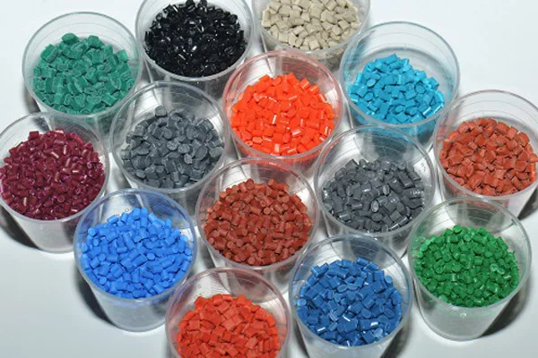
Plastic materials
2. Uniform Wall Thickness: The Key to Structural Integrity and Dimensional Stability
Maintaining a consistent wall thickness throughout a section is arguably the most critical rule in plastic injection molding design. Variations in wall thickness cause differential cooling rates, leading to a host of defects including sinks, warps, voids, and internal stresses that compromise the mechanical performance and cosmetic appearance of the part.
Technical Application and Considerations
Ideal Range: For most materials and part sizes, a wall thickness of 1.5mm to 3.0mm (0.060″ to 0.120″) provides an optimal balance of strength, cooling time, and material usage. This should be validated through flow simulation.
Managing Transitions: When changes in thickness are unavoidable, transition zones should be gradual, using a ratio of 3:1 (the length of the transition should be three times the change in thickness). Sudden changes create stress concentration points.
Ribs for Strength: Instead of thickening an entire section to add rigidity, use ribs. A rib should be 50-60% of the nominal wall thickness at its base to prevent sink marks on the opposite surface. The rib height should not exceed three times the nominal wall.
Boss Design: Bosses for screw assembly are common thick points. To avoid sinks and voids:
- Design the boss’s outer diameter to be approximately 2.5 times the screw’s major diameter.
- Connect the boss to walls via ribs, not by making the surrounding wall thicker.
- Consider using “core-outs” on the underside of the boss to maintain a more uniform wall.
Simulation is Essential: Modern mold flow analysis software can predict sink marks, warpage, and fill patterns based on wall thickness distribution, allowing for correction before tooling begins.
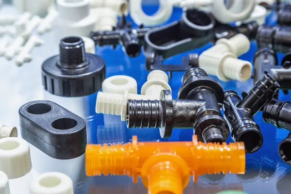
Plastic products
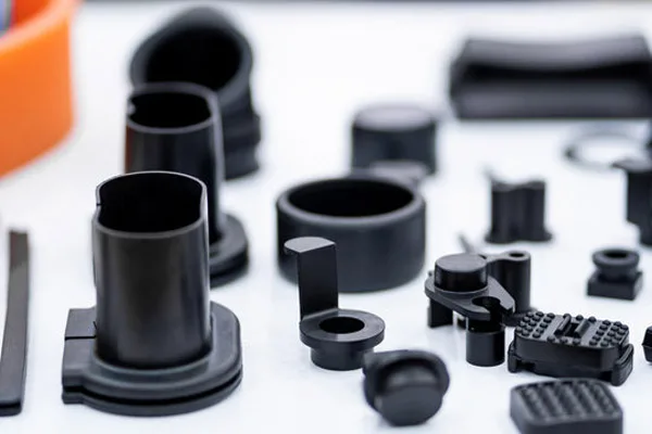
Plastic parts
3. Purpose-Driven Rib, Boss, and Corner Design
These foundational features require specialized geometry to function correctly without introducing manufacturing defects.
Technical Application and Considerations
Rib Design Details:
- Thickness: As noted, 50-60% of the adjoining wall.
- Draft: Apply adequate draft (often 0.5° to 1.5°) to the rib’s sides.
- Fillete: Use a radius at the base of the rib equal to 25-50% of the nominal wall to improve flow and reduce stress concentration.
- Spacing: Keep ribs spaced at a minimum of 2.5 times the nominal wall thickness apart.
Boss Design Details:
- Design with ample draft and a generous fillet at the base.
- For metal inserts, ensure the plastic wall around the insert is thick enough to withstand assembly and operational stresses without cracking.
Corner Design:
- Never use sharp corners. They act as stress concentrators, impede material flow, and are difficult to machine and polish in the mold.
- Apply radii to all internal and external corners. An internal radius should be a minimum of 0.5 times the wall thickness. The corresponding external radius will then be the internal radius plus the wall thickness, creating a uniform wall through the corner.
- Radii improve part strength, enhance flow, and extend mold life.
4. Optimizing Gate Location and its Influence on Design
The gate is the channel through which the molten plastic enters the cavity of the part. Its location dictates the flow path of the material, affecting weld lines, air traps, packing, orientation of fibers and, ultimately, the strength and appearance of the part. While the molder ultimately decides the gate location, the designer must anticipate and facilitate the optimal placement.
Technical Application and Considerations
Design for Flow: The part should allow plastic to flow smoothly from the gate to fill all extremities in a balanced manner. Long, unobstructed flow paths increase required injection pressure and can lead to premature freezing.
Weld Line Management: Weld lines form where separate melt fronts meet. They are inherently weak and can be cosmetically flawed. Design the part and propose gate locations to position weld lines in non-critical, low-stress areas. Adding “weld line stealers” (localized bumps) at anticipated weld locations can improve strength.
Venting Considerations: Air must escape the cavity as plastic fills it. Design should allow for vents at the end of fill, often in ejector pins or along parting lines. Deep, isolated pockets trap air and must be avoided or designed with adequate venting pathways.
Gate Types and Design Impact:
- Edge Gates: Common and simple. The design must allow for gate vestige (a small bump or scar) on the part periphery.
- Submarine/Tunnel Gates: Leave a small witness on the part’s underside, allowing automatic degating. The part must be designed to accommodate this.
- Direct or Sprue Gates: Used for large parts, leaving a significant mark. Often requires post-molding trimming.
- Hot Tip Gates: Leave a small, often circular, mark on the part surface. The designer must consider the cosmetic impact of this mark.
5. Specifying Tolerances: Realistic, Functional, and Moldable
Overly tight tolerances dramatically increase tooling cost, maintenance, process complexity, and part rejection rates. Tolerances must be driven by part function, not arbitrary drafting standards.
Technical Application and Considerations
Understand Process Capability: Standard commercial molding tolerances are typically in the range of ±0.1mm to ±0.5mm (±0.004″ to ±0.020″), depending on the material, part size, and feature. Holding tolerances below ±0.05mm (±0.002″) is considered precision molding and requires special materials, processes, and significant cost.
Critical vs. Non-Critical Dimensions: Identify truly critical interfaces and tolerance these specifically. Apply generous, standard tolerances to all non-critical features.
Geometric Tolerancing: Often more valuable than +/- linear tolerances. Use flatness, straightness, and position callouts to control warpage and alignment in a way that reflects actual function.
Material Matters: Crystalline materials (like Nylon, PP) shrink more and less predictably than amorphous materials (like ABS, PC). Fiber-filled materials shrink less in the direction of flow than across it. Always consult material-specific shrinkage data.
Mold Design Impact: Tight tolerances may require actions like interchangeable mold inserts, valve-gated hot runner systems for precise packing, or temperature-controlled mold zones, all adding to cost.
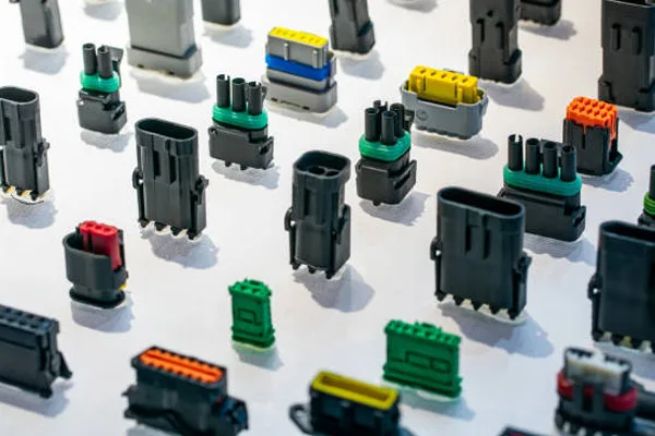
Plastic industrial terminal blocks
Conclusion: An Iterative, Collaborative Process
Mastering plastic part design is an iterative process that blends artistic vision with engineering discipline. The most successful designs emerged from early and sustained collaboration between product designers and plastic injection molding engineers. Leveraging tools such as CAD, DFM software, and mold flow simulation during the prototyping phase can de-risk projects and prevent costly mold modifications.
By religiously applying these five principles – ensuring adequate draft, maintaining uniform walls, designing intelligent ribs and bosses, planning for optimal gates, and specifying realistic tolerances – designers empower molders to produce high-quality, reliable, and cost-effective parts. This synergy between smart design and capable manufacturing is what turns a good concept into a great, market-ready product.